A Step-by-Step Guide to Creating Part Drawings in Engineering

In the realm of engineering, the creation of precise and detailed part drawings is a crucial step in the design and manufacturing process. These drawings serve as a bridge between the conceptualization of a product and its real-world manifestation. In this step-by-step guide, we will navigate through the fundamental elements involved in creating part drawings, shedding light on the methodologies employed in modern engineering practices.
Step 1: Understand the Part
Before embarking on the journey of creating a part drawing, it is imperative to have a comprehensive understanding of the part itself. Engineers must delve into the intricacies of the design, analyzing its geometry, dimensions, and material specifications. This foundational knowledge lays the groundwork for accurate and effective part drawings.
Step 2: Gather Necessary Information
Once the part is thoroughly understood, gather all pertinent information related to the design. This includes geometric dimensions, tolerances, material properties, and any specific manufacturing instructions. Collaborating with design teams and stakeholders ensures a holistic approach and minimizes the likelihood of errors.
Step 3: Utilize CAD Software
Modern engineering practices heavily rely on Computer-Aided Design (CAD) software for part drawing creation. These tools offer a versatile platform for designing and visualizing intricate details. Select a CAD software that aligns with the project requirements and leverage its features to accurately represent the part in a digital environment.
Step 4: Create the 3D Model
Begin the drawing process by creating a detailed 3D model of the part within the chosen CAD software. This step involves defining the part’s geometry, incorporating dimensions, and specifying any relevant features. The 3D model serves as the foundation for subsequent 2D drawings and aids in visualizing the final product.
Step 5: Generate Orthographic Views
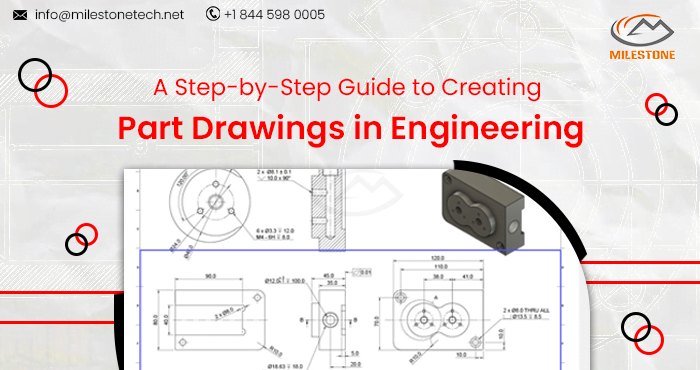
Orthographic views are essential for conveying the true shape and size of a part. Generate these views from the 3D model, representing the part in multiple planes (front, top, side, etc.). Each view should be accompanied by necessary dimensions, ensuring clarity in communication between design and manufacturing teams.
Step 6: Specify Tolerances and Annotations
Precision is paramount in engineering, and specifying tolerances ensures that the manufactured part meets the design intent. Add tolerances to dimensions, and include annotations to provide additional information to clarify specific features. This step is crucial for maintaining consistency and accuracy in the manufacturing process.
Step 7: Detailing and Section Views
To capture intricate details and internal features, incorporate detailing and section views into the part drawing. Detailing focuses on specific areas of interest, offering a closer look at critical features. Section views, on the other hand, cut through the part to reveal internal structures, enhancing the understanding of complex designs.
Step 8: Bill of Materials (BOM)
Create a comprehensive Bill of Materials that enumerates all the components required to assemble the final product. Include part numbers, quantities, and descriptions to facilitate efficient procurement and assembly processes.
Step 9: Review and Validation
Before finalizing the part drawing, undergo a thorough review process. Collaborate with cross-functional teams to validate the design, ensuring that all specifications are accurate and feasible for manufacturing. Address any discrepancies or potential issues during this collaborative phase.
Follow Milestone PLM Solutions for Mechanical Industry Updates, CAD Tips and Global Mechanical News.
Milestone PLM Solutions with its exclusive delivery center in India is a global CAD, Product Design partner serving the needs of the Mechanical Industry since 2004. MILESTONE focuses on the unique needs of clients and believe in tackling real-life problems with efficiency, smooth and ease.
We support multiple BIM software including SOLIDWORKS, AutoCAD, CATIA etc. Our approach is to provide a dedicated team for each customer over ongoing project and deliver the quality output consistently.
With our state of art technology and large talent pool of Engineers, we are developing best in class solutions for our customers across the globe. We align with your culture and values to form unbreakable partnerships and are primed for success with over 100 employees and 150 customers in the US, Europe, India, and Asia.
You can email us at info@milestonetech.net and can log in to our website www. milestonetech.net to know more about our services and our work portfolio or contact us on +1-844-598-0005
