Mastering Limits, Fits, and Tolerances: Key to Precision Engineering

The hallmark of any successful engineering project lies in its precision. Whether it’s a towering skyscraper or a miniature circuit board, the seamless interaction of components hinges on a critical concept: Limits, Fits, and Tolerances (LFT). Understanding and mastering these principles is the foundation for ensuring the functionality, interchangeability, and overall success of your designs.
Limits: Defining the Boundaries
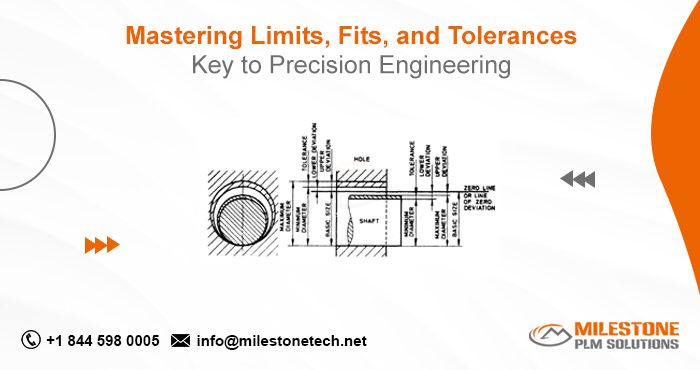
Limits represent the absolute permissible extremes for a specific dimension. Imagine a shaft – its nominal size might be 10 millimeters (mm). However, due to manufacturing limitations and practical considerations, it’s impossible to achieve this exact size consistently. Limits define the acceptable range for this shaft’s diameter. For example, the upper limit might be 10.1 mm and the lower limit 9.9 mm. Any shaft manufactured within this range (9.9 mm to 10.1 mm) is considered acceptable.
Tolerance: The Permissible Variation
Tolerance bridges the gap between limits. It signifies the total allowable deviation from the nominal size. In our shaft example, the tolerance is 0.2 mm (10.1 mm – 9.9 mm). A tighter tolerance signifies a smaller range of acceptable variation, resulting in a more precise fit. Conversely, a larger tolerance allows for more manufacturing flexibility but might lead to looser fits.
Fits: The Dance of Two Parts
The relationship between mating parts, defined by the difference in their sizes, is known as the fit. There are three primary categories of fits:
- Clearance Fit: Here, the hole is always larger than the shaft. This allows for free movement between the parts, ideal for applications requiring smooth rotation or linear motion (e.g., bearings, gears).
- Interference Fit: In this scenario, the shaft is larger than the hole. The parts require pressure or force for assembly, creating a tight, immobile joint. This fit is suitable for applications demanding high strength and minimal movement (e.g., press-fit components, flywheels).
- Transition Fit: This falls between clearance and interference fits. The largest shaft might be larger than the smallest hole, but the smallest shaft could also be larger than the largest hole. This fit allows for some assembly variability and is used in situations where precise location control is less critical.
Selecting the Right Fit
The choice of fit depends on the intended function of the assembly. Here are some key factors to consider:
- Required Motion: Clearance fits are ideal for smooth operation, while interference fits prevent movement.
- Strength and Rigidity: Interference fits create strong, immovable joints, while clearance fits offer less structural support.
- Assembly Efficiency: Clearance fits are easier to assemble, while interference fits might require specialized techniques.
- Thermal Expansion: Materials expand with heat. Clearance fits account for this expansion, while interference fits might require specific considerations.
Standards and Systems: A Universal Language
To ensure consistent interpretation and application of LFT principles, standardized systems are employed. The International Organization for Standardization (ISO) defines tolerance grades (IT grades) that specify acceptable tolerance ranges for different size classes. Similarly, standard fit systems like the ISO hole-based system categorize fits based on their application and tolerance values.
Benefits of Mastering LFT
Mastering LFT offers several advantages:
- Improved Functionality: Precise fits ensure components operate as intended, minimizing friction, wear, and noise.
- Enhanced Interchangeability: Standardized LFT practices allow for assembling parts from different sources without compromising functionality.
- Reduced Manufacturing Costs: Optimizing tolerances can streamline manufacturing processes by minimizing rejection rates and rework.
- Reliable Performance: Precise LFT ensures consistent performance and extends the lifespan of your products.
Conclusion
Limits, Fits, and Tolerances are the cornerstones of precision engineering and product design and development. By mastering these concepts and applying them effectively, you can create robust, functional, and interchangeable components, establishing a solid foundation for successful projects. Remember, a deep understanding of LFT is not merely about numbers; it’s about developing a language that guarantees the seamless integration of your designs, bringing your vision to life with exceptional precision.
Follow Milestone PLM Solutions for Mechanical Industry Updates, CAD Tips and Global Mechanical News.
Milestone PLM Solutions with its exclusive delivery center in India is a global CAD, CAM & FEA services outsourcing partner serving the needs of the Mechanical, Millwork and Automotive industry since 2004. MILESTONE focuses on the unique needs of clients and believes in tackling real-life problems with efficiency, smooth and ease.
The MILESTONE team can assist you with Product Design, 3d Modeling, Drafting & detailing, Reverse Engineering, FEA Analysis and more. We support multiple software including AutoCAD, SolidWorks, Catia, NX, Inventor, Solidedge & Ansys etc. Our approach is to provide a dedicated team for each customer over ongoing project and deliver the quality output consistently.
With our state of art technology and large talent pool of Engineers, we are developing best in class solutions for our customers across the globe. We align with your culture and values to form unbreakable partnerships and are primed for success with over 100 employees and 150 customers in the US, Europe, India, and Asia.
