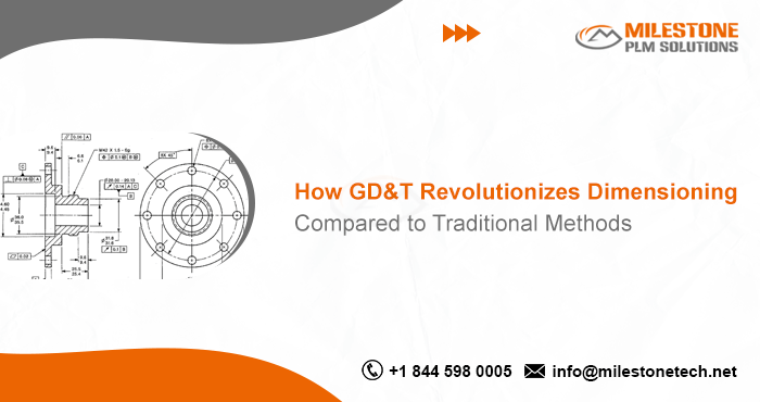
How GD&T Revolutionizes Dimensioning Compared to Traditional Methods

GD&T Revolutionizes: For decades, the manufacturing industry relied on traditional dimensioning methods to communicate part specifications. This approach involved simply listing linear dimensions and tolerances on engineering drawings. While seemingly straightforward, traditional methods often led to ambiguity and misinterpretations, resulting in parts that didn’t function as intended. Geometric Dimensioning and Tolerancing (GD&T), however, has revolutionized the way engineers define and communicate part characteristics.
The Limitations of Traditional Dimensioning
Traditional dimensioning focuses solely on specifying the size and location of features on a part using linear dimensions like lengths, widths, and heights. Tolerances are then added to account for manufacturing variations. However, this approach fails to capture the critical aspect of how parts interact with each other functionally. Here’s how traditional methods fall short:
- Focus on Form, Not Function: Traditional methods prioritize the size and location of features without considering how those features influence the part’s ability to perform its intended function.
- Ambiguity in Interpretation: Drawings with only linear dimensions can be open to interpretation. Different manufacturers might interpret the same drawing differently, leading to inconsistencies in part production.
- Limited Control of Functionality: Traditional methods lack the ability to specify how a part should interact with its mating components. This can result in parts that fit dimensionally but malfunction when assembled.
The Power of GD&T
GD&T Revolutionizes overcomes the limitations of traditional methods by introducing a standardized language of symbols and annotations. This language enables engineers to define not only the size and location of features but also their geometric form and orientation. When integrated with CAD and detailing, GD&T ensures precise and consistent communication of design intent, enhancing accuracy in manufacturing and inspection processes. Here’s how GD&T revolutionizes dimensioning:
- Focus on Functionality: GD&T goes beyond size and location by specifying tolerances for form (flatness, roundness, etc.) and orientation (runout, angularity, etc.). This ensures parts function correctly when assembled.
- Clear Communication: The standardized symbols of GD&T eliminate ambiguity in interpretation. Everyone involved in the manufacturing process, from engineers to inspectors, understands the exact requirements for each feature.
- Improved Quality and Efficiency: By focusing on functionality, GD&T reduces the likelihood of errors and rework during production. This leads to higher quality parts and improved manufacturing efficiency.
- International Language: The standardized symbols of GD&T transcend language barriers, facilitating seamless collaboration between international design and manufacturing teams.
Key Elements of GD&T
GD&T utilizes a specific set of symbols and annotations to convey design intent. Here are some of the key elements:
- Datums: These are theoretically perfect reference surfaces used to define the location and orientation of other features.
- Form Tolerances: These tolerances control the shape of a feature, such as flatness, roundness, straightness, etc.
- Positional Tolerances: These tolerances control the location of a feature relative to a datum. Examples include location, concentricity, and runout.
- Orientation Tolerances: These tolerances control the angular relationship between a feature and a datum. Examples include angularity and parallelism.
Benefits of Using GD&T
The adoption of GD&T offers a multitude of benefits throughout the manufacturing process:
- Improved Product Quality: By clearly defining functional requirements, GD&T ensures parts are manufactured to perform as intended. This leads to a higher quality final product.
- Reduced Manufacturing Costs: By minimizing errors and rework, GD&T improves production efficiency and reduces overall manufacturing costs.
- Enhanced Communication: The standardized language of GD&T fosters clear communication between design, manufacturing, and inspection teams, minimizing misunderstandings.
- Global Collaboration: GD&T facilitates seamless collaboration between international teams working on the same project.
Conclusion
GD&T represents a significant leap forward in how parts are designed, manufactured, and assembled. By moving beyond simple dimensions to focus on functionality, GD&T ensures parts not only fit together but also perform as intended. In today’s globalized manufacturing environment, GD&T is an essential tool for engineers and manufacturers seeking to produce high-quality products efficiently.
Follow Milestone PLM Solutions for Mechanical Industry Updates, CAD Tips and Global Mechanical News.
Milestone PLM Solutions with its exclusive delivery center in India is a global CAD, CAM & FEA services outsourcing partner serving the needs of the Mechanical, Millwork and Automotive industry since 2004. MILESTONE focuses on the unique needs of clients and believes in tackling real-life problems with efficiency, smooth and ease.
The MILESTONE team can assist you with Product Design, 3d Modeling, Drafting & detailing, Reverse Engineering, FEA Analysis and more. We support multiple software including AutoCAD, SolidWorks, Catia, NX, Inventor, Solidedge & Ansys etc. Our approach is to provide a dedicated team for each customer over ongoing project and deliver the quality output consistently.
With our state of art technology and large talent pool of Engineers, we are developing best in class solutions for our customers across the globe. We align with your culture and values to form unbreakable partnerships and are primed for success with over 100 employees and 150 customers in the US, Europe, India, and Asia.
You can email us at info@milestonetech.net and can log in to our website www. milestonetech.net to know more about our services and our work portfolio or contact us on +1-844-598-0005
