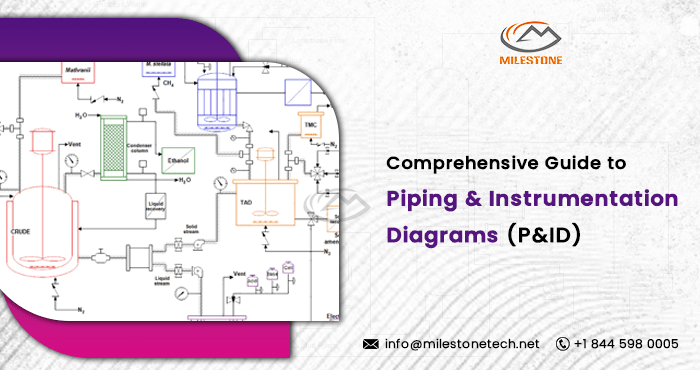
Comprehensive Guide to Piping and Instrumentation Diagrams (P&ID)

Piping and Instrumentation Diagrams (P&ID) are essential tools in the field of engineering, particularly in the realm of construction and process industries. These detailed schematics provide a visual representation of the interconnecting components within a system, offering invaluable insights into the design and functionality of complex processes. In this comprehensive guide, we will delve into the fundamentals of P&IDs, their significance, and the key elements that constitute these crucial engineering documents.
Understanding Piping and Instrumentation Diagrams:
A Piping and Instrumentation Diagram is a schematic representation of a process flow within a facility. It illustrates the relationships between various components such as pipes, vessels, valves, and instrumentation, enabling engineers and stakeholders to comprehend the intricacies of a system at a glance. P&IDs play a pivotal role in the design, construction, and maintenance of industrial plants, ensuring efficiency, safety, and compliance with regulatory standards.
Key Components of P&IDs:
- Piping Components: Piping elements are depicted using standardized symbols to represent different pipe types, sizes, and connections. The direction of flow is indicated by arrows, providing a clear understanding of the process sequence.
- Process Equipment: Equipment such as pumps, compressors, heat exchangers, and tanks are prominently featured in P&IDs. Each piece of equipment is represented by a unique symbol, accompanied by essential information like size, capacity, and specifications.
- Instruments and Control Devices: Instruments, sensors, and control devices are crucial aspects of P&IDs. Symbols for transmitters, level indicators, pressure gauges, and control valves are included to convey the monitoring and control aspects of the system.
- Valves: Different types of valves, including gate valves, globe valves, and ball valves, are illustrated in P&IDs. Valve symbols provide information on their functions, such as isolation, throttling, or relief.
- Lines and Symbols: Various lines on P&IDs represent different pipe specifications, such as process lines, instrument lines, and utility lines. Symbols for instruments and equipment are standardized across industries, ensuring a universal understanding of the diagrams.
Significance of P&IDs in Engineering:
- Design and Engineering: P&IDs serve as the foundation for designing a system. Engineers use these diagrams to conceptualize and plan the layout of a facility, ensuring that all components work cohesively to achieve the desired outcome.
- Safety and Compliance: P&IDs play a crucial role in ensuring the safety of industrial processes. By providing a visual representation of the entire system, potential hazards can be identified, and safety measures can be implemented to comply with regulatory standards.
- Operation and Maintenance: During the operational phase, P&IDs aid in troubleshooting, maintenance, and system upgrades. They serve as invaluable references for technicians and maintenance personnel, offering a comprehensive overview of the system’s architecture.
- Communication and Collaboration: P&IDs act as a universal language in the engineering domain. They facilitate effective communication between different stakeholders, including designers, engineers, operators, and maintenance personnel, ensuring a common understanding of the system.
Conclusion of piping and instrumentation diagram
In conclusion, Piping and Instrumentation Diagram are indispensable tools in the field of engineering, especially for those involved in construction and process industries. Their ability to provide a comprehensive visual representation of complex systems enhances the design, safety, and efficiency of industrial processes. As technology continues to advance, the integration of P&IDs with AI tools and new technologies promises even greater precision and optimization in the engineering realm, further solidifying their significance in shaping the future of the industry.
Follow Milestone PLM Solutions for Mechanical Industry Updates, CAD Tips and Global Mechanical News.
Milestone PLM Solutions with its exclusive delivery center in India is a global CAD, Product Design partner serving the needs of the Mechanical Industry since 2004. MILESTONE focuses on the unique needs of clients and believe in tackling real-life problems with efficiency, smooth and ease.
We support multiple BIM software including SOLIDWORKS, AutoCAD, CATIA etc. Our approach is to provide a dedicated team for each customer over ongoing project and deliver the quality output consistently.
With our state of art technology and large talent pool of Engineers, we are developing best in class solutions for our customers across the globe. We align with your culture and values to form unbreakable partnerships and are primed for success with over 100 employees and 150 customers in the US, Europe, India, and Asia.
You can email us at info@milestonetech.net and can log in to our website www. milestonetech.net to know more about our services and our work portfolio or contact us on +1-844-598-0005
