Guide to Understanding Projections in Engineering Drawings

Engineering drawings allow objects to be represented on paper or on a computer screen. The view seen represents only one side of the object and that side changes as you “turn” the illustration. All three dimensions of an object are devoted to single image in a construction drawing.
Engineers must be able to read and interpret drawings. They need to know the spatial relations that are included in these drawings.
What does a projection mean in engineering drawing?
Engineering drawings are a way of communicating to others what your object will look like and offer a means of conveying information to those who understand these drawings.
An image that is represented on a surface or plane is referred to as a projection. It could be an image of any object like a point, line, plane, solid, machine component, or building.
Technical drawings can create projections based on where the person is looking as well as the direction of where the projector is showing. Projections are created on a 2D surface, often technical drawing paper, that represent a 3D model. In technical drawings, projectors simulate a 3D part’s view onto the projection plane. Alternatively, some parts can be only simulated in model form.
Various types of projections in engineering drawings
3-D projections are useful for generating an image similar to what the designer can produce in their mind. However, the object is frequently distorted and detail is absent from 3-D projection images.
In a typical 3D image, the viewing angle often doesn’t show all of an object’s details. Multi-view projections, however, provide more accurate representations of objects and can accurately depict circular holes. Combining 3D projections with Multi-view projections results in a much more detailed depiction of the object.
By projecting in 3D or using the Multi-view projection, you can see a perfect representation of what the object looks like.
3D Projections

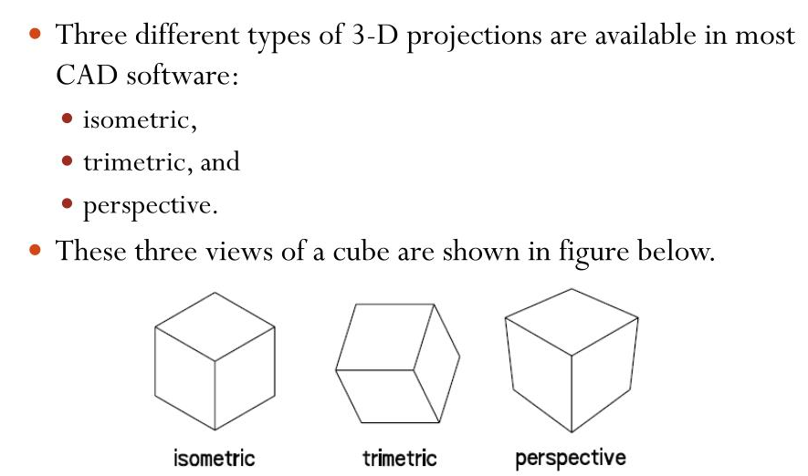
CAD software generally has three 3-D projections: isometric, trimetric, and perspective. All three representations give a tridimensional representation of an object in a 2-D image. Advantages to each are noted as well as disadvantages.
- Isometric Projection – The isometric projection has a standard orientation, making it the most popular and widely used projection in CAD drawings. Isometric projection are drawn at 30° above horizontal for width and depth. This results in all three angles at a corner becoming 120°.
Isometric drawings are best for objects with limited depth. When there is significant amount of depth, the drawings which are isometric distort the object. Pictorial perspective drawings are preferred in this case.
- Trimetric Projection – The trimetric projection allows you to stretch your object in three dimensions using uneven angles. This provides you more options when arranging the object in space. Trimetric comes from the Latin word for three + metrical which means measure of distance.
Trimetric views are projections of the three angles between axes, with a separate scale needed to create them.
- Perspective Projection – A pictorial perspective projection creates a realistic depiction of objects by following their parallel lines. A bridge will remain parallel, but at a distance in perspective projection.
With isometric and trimetric views, you can better represent manufactured items quickly. In relation to 3-D CAD projections, The isometric projection is very effortless to draw sketch of an item very realistically in relation to 3D CAD projection. This is frequently used in freehand sketching.
The oblique projection is easier to draw because the major face of the object is parallel to the surface of the paper. The axes in the plane of the paper are perpendicular, and the surface of the paper is angled at an arbitrary angle.
You can use this projection because it keeps the true contour of details on the front face, gives a round rather than elliptical circle, and is easier than isometric sketching.
Multi-view Projections

Multi-view projections are good for revealing the intricacies of objects, and they can maintain the integrity of a 3-D shape. An immediately recognizable visual representation of an object is created by 3D projections.
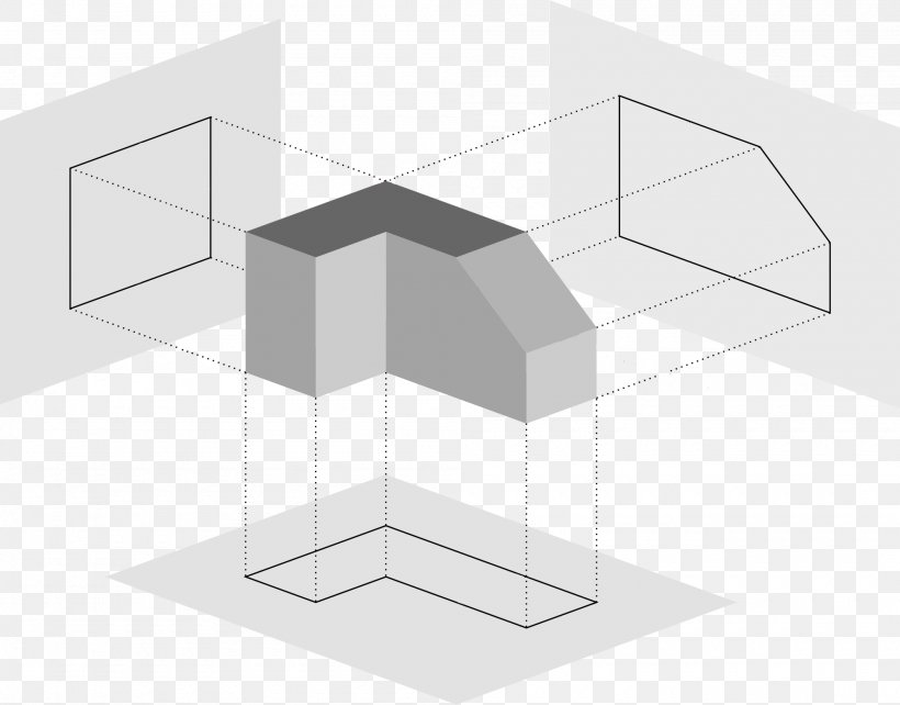
A Multiview projection is a way to show the shape of a three-dimensional object by using a standard set of orthographic two-dimensional pictures. Each projection plane is parallel to one of the object’s coordinate axes, producing up to six primary views of the object. One of two strategies is used to position the views in relation to one another: either a projection at the first or third angle. The views’ appearances can be thought of as being projected onto planes that surround the object in a six-sided box in each. Albeit six distinct sides can be drawn, typically three perspectives on an attracting give sufficient data to make a three-layered object. Front view, top view, and end view are the names of these views. Different names for these perspectives incorporate arrangement, rise and segment.
- Orthographic Projection – Orthography projections are the common method of displaying multiple views of an object in engineering graphics. You can create two orthographic projections of a coffee mug, one which is the front and one which is the side wall.
The engineering drawing of the cup you are drinking will show the dimensions of just the mug, the rim at the top, and how the handle attaches to it.
An easy way to add dimensions of the cup to a drawing of the mug would be to project and draw each side of the cup onto the side of the mug.
This article is designed to help you identify the common types of projections in engineering and CAD drawings.
Follow Milestone PLM Solutions for Mechanical Industry Updates, CAD Tips and Global CAD, CAM & FEA News.
Milestone PLM Solutions with its exclusive delivery center in India is a global CAD, CAM & FEA services outsourcing partner serving the needs of the Mechanical, Millwork and Automotive industry since 2004. MILESTONE focuses on the unique needs of clients and believe in tackling real-life problems with efficiency, smooth and ease.
The MILESTONE team can assist you with Product Design, 3d Modeling, Drafting & detailing, Reverse Engineering, FEA Analysis and more. We support multiple software including AutoCAD, Solidworks, Catia, NX, Inventor, Solidedge & Ansys etc. Our approach is to provide a dedicated team for each customer over ongoing project and deliver the quality output consistently.
With our state of art technology and large talent pool of Engineers, we are developing best in class solutions for our customers across the globe. We align with your culture and values to form unbreakable partnerships and are primed for success with over 100 employees and 150 customers in the US, Europe, India, and Asia.
For more queries regarding any of the above-mentioned topics, feel free to connect with us on our website www.milestonetech.net or contact us on +1-844-598-0005
